- Research
- Open access
- Published:
Robust video steganography for social media sharing based on principal component analysis
EURASIP Journal on Information Security volume 2022, Article number: 4 (2022)
Abstract
Most social media channels are lossy where videos are transcoded to reduce transmission bandwidth or storage space, such as social networking sites and video sharing platforms. Video transcoding makes most video steganographic schemes unusable for hidden communication based on social media. This paper proposes robust video steganography against video transcoding to construct reliable hidden communication on social media channels. A new strategy based on principal component analysis is provided to select robust embedding regions. Besides, side information is generated to label these selected regions. Side information compression is designed to reduce the transmission bandwidth cost. Then, one luminance component and one chrominance component are joined to embed secret messages and side information, notifying the receiver of correct extraction positions. Video preprocessing is conducted to improve the applicability of our proposed method to various video transcoding mechanisms. Experimental results have shown that our proposed method provides stronger robustness against video transcoding than other methods and achieves satisfactory security performance against steganalysis. Compared with some existing methods, our proposed method is more robust and reliable to realize hidden communication over social media channels, such as YouTube and Vimeo.
1 Introduction
Steganography is the art and science of covert communication, which embeds secret messages into digital media without arousing any suspicion. Due to the widespread popularity of social media applications and the continuous improvement in video coding technology, digital video has become one of the most influential media. Additionally, according to Cisco Annual White Paper, the number of global Internet users will grow to 66% of the global population by 2023 [1]. Video-sharing based on social media could serve as an ideal cloak for covert communication. Video steganography for social media becomes a research hotspot in the field of information hiding.
Compared with traditional hidden communication, the model of hidden communication based on social media has more advantages and better security. Zhao et al. [2] have reviewed the sharing-based model of hidden communication. The traditional hidden communication is one-to-one communication. One sender is associated with one receiver. The transmitted multimedia is identical to the original. The observer can monitor the secret communication between the sender and receiver. In contrary to traditional hidden communication, hidden communication based on social media is one-to-many communication. Generally, the transmission of steganographic multimedia is lossy. As illustrated in Fig. 1, videos shared by the sender are available for anyone with access to the social media sharing platform. The sender can pass secret messages to many receivers. But the observer cannot even distinguish the receivers from ordinary users. The one-to-many sharing characteristic of social media provides good concealment and security to protect both participants in the communication. Moreover, most video-sharing channels transmit the steganographic video in a lossy way to reduce transmission bandwidth or storage space, such as YouTube and Twitter. Videos that have not been transcoded cannot be retrieved for steganalysis. To take advantage of social media channels for hidden communication, researching robust steganography for social media sharing is urgent and essential.

The model of hidden communication based on social media sharing. The sender uploads the stego video to social media platforms or sites. The receivers download the transcoded video for secret message extraction. Hidden communication is carried out based on social media sharing. S represents the stego video carried with secret messages. S’ is the transcoded version of S
The research on robust steganography develops rapidly. There is extensive research on robust image steganography. Kin-Cleaves et al. [3] proposed an extension of Syndrome Trellis Codes (STCs) and combined error correction codes to achieve adaptive steganography in noisy channels. Zhao et al. [4] proposed a robust steganographic algorithm to resist the JPEG compression of transport channels based on transport channel matching. Tao et al. [5] proposed a robust image steganographic framework to make covert communication over social networks. Zhang et al. [6] proposed robust image steganography in a robust domain based on STCs with Reed-Solomon (RS) codes.
Compared with robust image steganography, robust video steganography is still at the initial stage. Video steganography can be divided into two categories: compressed domain steganography and spatial domain steganography. Compressed domain steganography modulates syntax elements to embed secret messages, such as motion vectors [7–9], prediction modes [10, 11], and quantized discrete cosine transform (DCT) coefficients [12]. However, the encoding standards and parameters of the video encoder are unknown on a given social media channel. The changes of these syntax elements are unpredictable in the process of video transcoding. Thus, compressed domain video steganography is not robust for hidden communication based on social media. Spatial domain video steganography embeds secret messages in the spatial domain or spatial transform domain. The spatial domain includes red, green, blue (RGB) color components [13], YUV (luminance, chrominance) components, and color histograms [14, 15]. The spatial transform domain includes the DCT domain [16], discrete wavelet transform (DWT) domain [17, 18], singular value decomposition (SVD) domain, and their variants. Compared with compressed domain video steganography, spatial domain and spatial transform domain video steganography can provide certain robustness against video transcoding.
Currently, the research on robust video information hiding concentrates on the spatial transform domain, including robust video watermarking and steganography. Essentially, both robust video watermarking and robust video steganography conduct message embedding into digital video. Robust video watermarking aims to protect the video from illegal distribution whereby additional information, called a watermark. Robust watermarking pays much attention to the robustness against geometric attacks and lossy compression but does not care about the embedding capacity and security. Robust video steganography aims to send secret messages to the receiver through lossy channels without arousing any suspicions from the observer. Thus, the robustness against lossy channels, the security against steganalysis, and the embedding capacity are equally important.
In robust watermarking, Esfahani et al. [19] proposed a robust video watermarking algorithm based on dual-tree complex wavelet transform. This algorithm is robust against video compression, scaling, and rotation attacks. However, statistical security and embedding capacity are not considered. In robust steganography, Mstafa et al. [20] proposed a robust video steganographic method based on multiple objects tracking in the DWT-DCT domain. Dalal et al. [21] proposed a video steganographic scheme based on multiple moving objects tracking. These two methods improve the robustness by selecting embedding regions and Bose–Chaudhuri–Hocquenghem (BCH) codes. However, when video transcoding happens in lossy channels, it is not considered how to ensure the extraction regions are the same as the embedding regions. Fan et al. [22] proposed a robust video steganographic method against social networking transcoding. The method improves robustness by selecting robust frames and BCH codes. Besides, a side channel is constructed as the synchronic signal to determine the extraction location. However, there are some non-robust regions in the built side channel, which makes the side channel sensitive to video transcoding. Thus, the bit error rate (BER) is still high, and the failure of message extraction is even possible.
In general, these existing robust steganographic schemes are still not robust enough to construct hidden communication on social media channels. Besides, it is not entirely solved to pinpoint the exaction locations at the receiver in region selection-based steganography. To construct reliable hidden communication on social media, we should enhance the robustness as much as possible and improve the applicability over various channels. Besides, it is significant to ensure the synchronization of the embedding and extraction regions.
In this paper, we propose robust video steganography against video transcoding for social media-based hidden communication. First, cover videos are decoded to the spatial domain. Frames are decomposed into a luminance component (Y) and two chrominance components (U and V). Second, principal component analysis (PCA) is used to select appropriate embedding regions adaptively. Side information is generated to flag these selected regions. Third, these selected regions in the Y component are embedded with secret messages based on quantized index modulation (QIM), and the side information is embedded into the U component. Finally, modulated Y and U components are encoded with the V component to generate stego videos. Besides, video preprocessing is introduced to improve the applicability of our proposed method to various social media channels. Compared with some existing methods, our proposed method is more robust and reliable to realize hidden communication over social media channels, such as YouTube and Vimeo. The main contributions of this paper are summarized as follows.
-
(1)
An adaptive robust steganographic method is proposed to construct hidden communication based on social media. The BER of our proposed method is lower than state-of-the-art algorithms.
-
(2)
Principal component analysis is first used to select the appropriate embedding regions, enhancing the robustness against video transcoding.
-
(3)
A dual-channel embedding scheme is proposed based on the Y and U components to realize the synchronization of the embedding and extraction sides.
The remainder of this paper is organized as follows. In Section 2, the basic concepts of video transcoding, the DWT-SVD domain, and modulation are described. In Section 3, the proposed method is illustrated in detail. Section 4 explains the experimental settings and parameters. Experimental results and discussion are provided in Section 5. Finally, Section 6 concludes this paper and discusses the future work.
2 Preliminaries
Some preliminaries need to be explained before introducing our proposed method, including video transcoding on social media, the construction of DWT-SVD domain, robust modulation, and channel coding.
2.1 Video transcoding
Video transcoding is common on social media channels. Moreover, their video transcoding mechanisms are not open-source to users, such as YouTube and Vimeo. Each channel is a black box, and users can only obtain the input and output of it. Generally, the resolution, frame rate, and coding standard can be maintained if they are typical specifications. For example, supported resolutions include 480p (640×480), 720p (1280×720), 1080p (1920×1080), and so on. Accepted frame rates are 24, 25, and 30 frames per second. Standard codecs include H.264/AVC [23] and H.265/HEVC [24]. However, the encoding parameters are changed unpredictably, such as bitrate, quantization parameters (QPs) of macroblocks, motion vectors, DCT coefficients, and group of pictures (GOP) structures. Most social media channels compress the uploaded video but keep the resolution unchanged. Thus, this paper aims to construct reliable hidden communication against video transcoding, where the resolution remains unchanged.
2.2 DWT-SVD domain
DWT-SVD domain is a commonly used embedding domain in robust steganography, built by jointly performing DWT and SVD. DWT can capture the specific features from low-level frequency to high-level frequency. As shown in Fig. 2, one level of DWT decomposition produces four frequency subbands, namely LL, LH, HL, and HH. As the low-frequency subband, LL concentrates intense energy and has a certain degree of stability. Liu et al. [25] have summarized two properties of SVD from the perspective of image processing:
-
(1)
The singular values of an image have strong stability. If the small perturbation is added to an image, the singular values do not change significantly.
Fig. 2 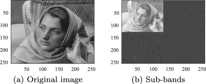
One level of DWT decomposition
-
(2)
The singular values represent intrinsic algebraic image properties. Utilizing SVD can capture the critical information implicit in the matrix. The importance is positively correlated with the magnitude of the singular values.

Robust elements are extracted based on DWT and SVD, which can resist video transcoding on lossy channels. Especially in SVD, the maximum singular value has the most strong stability and is less affected by signal processing [26]. In this paper, the maximum singular value of the LL subband is calculated by combining DWT with SVD, and robust elements are extracted from pixel blocks.
A given frame with the size of w×h can be divided into non-overlapping n×n blocks. The embedding matrix F is defined as:
where u=⌊h/n⌋ and v=⌊w/n⌋ denote the row and column numbers of blocks, respectively, and xij represents the block of the ith row and the jth column. If u=h/n and v=w/n, the embedding matrix F is the given frame itself. Then, high-pass and low-pass filters are used to conduct DWT. xij is transformed to produce four frequency subbands, namely \(\mathbf {x}^{\text {LL}}_{{ij}}\), \(\mathbf {x}^{\text {LH}}_{{ij}}\), \(\mathbf {x}^{\text {HL}}_{{ij}}\), and \(\mathbf {x}^{\text {HH}}_{{ij}}\). \(\mathbf {x}^{\text {LL}}_{{ij}}\) represents the low-frequency sub-band of DWT. Perform SVD, and \(\mathbf {x}^{\text {LL}}_{{ij}}\) can be decomposed as:
where Uij and Vij are both unitary matrices. Sij is a diagonal matrix given by:
where r is the rank of Sij and represents the number of nonzero singular values. The singular values satisfy the property that \(s_{{ij}}(1) \geqslant s_{{ij}}(2) \geqslant... \geqslant s_{{ij}}(r) \geqslant 0\). Thus, the robust element matrix E of a given frame is extracted by selecting the maximum singular value of each block and formulated as:
where \(s^{1}_{{ij}}\) is the maximum singular value of xij. For a video consisting of t frames, the corresponding robust domain ED is described by:
where Ek is the robust element matrix of the kth frame.
2.3 Robust modulation
The least significant bit modulation is a basic embedding method in information hiding. After that, matrix encoding [27, 28] and STC [29] have been proposed successively. These steganographic codes improve embedding efficiency and security. However, robustness is not considered. In order to improve the robustness against various kinds of noise, QIM algorithm [30] and its variant [31] are proposed.
In this paper, QIM is used to modulate robust elements extracted from the DWT-SVD domain. Given a binary secret message sequence M and cover sequence R, the embedding process of QIM is explained by:
where \(R^{\prime }_{i}\) is the stego element, Δ1 represents the quantization step size of QIM, mi∈M, and Ri∈R.
2.4 Channel coding
In covert communication over lossy channels, channel coding is commonly used to recover the error bits caused by noise. Channel coding is performed at the sender as an encoder, and extra bits are added with the raw data. At the receiver, channel coding is portrayed as the decoder to detect and correct error bits. In general, the more robust channel coding induces more redundancy that needs to be transmitted, reducing the effective bitrate but improving accuracy.
BCH codes [32, 33] and RS codes [34] are two classes of typical channel coding techniques. BCH codes are suitable to recover random errors and are widely used in robust information hiding [35–37]. In contrary to BCH codes, RS codes are suitable for correcting burst errors and are often used in conjunction with STC [3, 38]. In this paper, BCH codes are used to eliminate error bits in the side information. Secret messages can also be encoded utilizing BCH codes to improve the success rate of covert communication.
3 Proposed method
In this section, robust video steganography against video transcoding is proposed for hidden communication based on social media. The PCA-based strategy is first presented to select robust embedding regions. Then, side information compression is conducted to reduce the transmission bandwidth cost. Besides, video preprocessing is used to improve the applicability of our method over various social media channels. Channel coding is introduced to enhance the robustness against video transcoding. Finally, dual-channel joint embedding and extraction processes based on the Y and U components are described.
The overall steganographic framework is shown in Fig. 3. First, decode the cover video to generate the YUV components sequence. Then, embed secret messages into the Y component and side information into the U component. At last, encode modulated YUV components sequence to generate the stego video. It is worth mentioning that using BCH codes to encode secret messages is optional. Error correction bits can be introduced to reduce the bit error rate but decrease the available message capacity. In the experiments, BCH codes are used to analyze their error correction capacity.

The steganographic framework based on PCA selection. EDY and EDU are the embedding domains constructed from the Y and U components, respectively. SI is the side information that labels PCA-selected regions. Y, U, and V represent the luminance and chrominance components. Ystego and Ustego are the steganographic version of Y and U, respectively
3.1 PCA selection of embedding regions
Video transcoding introduces different levels of noise to different regions in a video. Different noise levels affect different frames, and different areas are affected by noise differently, even within the same frame. Thus, the most direct way of improving robustness is to select those robust regions less affected by video transcoding. In [22], two-thirds of frames are selected as robust frames to carry secret messages in a video. There are still some regions sensitive to video transcoding even within a selected robust frame. Thus, the BER of their method is still high. It is necessary to score pixel blocks in a given video to select robust blocks against video transcoding.
Principal component analysis is the process of computing the principal components. Sometimes, only the first few principal components are used, and the rest principal components are ignored. The proportion of the first principal component reflects the distribution characteristics of data. In video transcoding, the number of bits to code the prediction residuals of macroblocks changes. The low-frequency DCT coefficients are retained, but most high-frequency DCT coefficients become 0. Video transcoding makes a great impact on the macroblocks, the prediction residuals of which have a large proportion of high-frequency DCT coefficients. The blocks with a large proportion of low-frequency DCT coefficients should be the preferred option for message embedding. Moreover, the larger the proportion of low-frequency DCT coefficients is, the larger the proportion of the first principal component is. Thus, the proportion of the first principal component is a reasonable and straightforward guideline to score pixel blocks.
In this paper, the proportion of the first principal component in the DWT domain is calculated as the assessment criteria to determine robust embedding regions. Video frames are divided into non-overlapping n×n blocks. PCA is performed on each block in a frame, and the proportion of the first principal component is calculated. A threshold T is elaborately set for the selection of robust blocks. The blocks whose proportion of the first principal component is greater than T are selected as robust blocks and marked as “0.” The remaining blocks are labeled as “1.”
For a given block X, DWT is performed to obtain the LL sub-band. Next, PCA is conducted by:
where XLL is the LL sub-band of X, n is the size of X, and C is the covariance matrix of XLL. SVD is performed as XLL=UΣVT where UUT=I, VVT=I. The proportion p1 of the first principal component is calculated by:
where the diagonal matrix Σ=diag(σ1,σ2,...,σr,...,0) is the singular values matrix, and r represents the number of nonzero singular values.
A simple test is realized to verify the effectiveness of PCA. A randomly selected video with 180 frames is transcoded by a transcoder with the constant rate factor (CRF) value of 26. The average mean square error (MSE) of regions within each frame is shown in Fig. 4. The average MSE of PCA-selected regions is 56% of all regions and 11% of non-PCA-selected regions. The experimental result has illustrated that PCA is effective in selecting the regions less affected by video transcoding.

The average MSE of all regions, PCA-selected regions, and non-PCA-selected regions within each frame
3.2 Side information compression
The side information, formed by all labels of pixel blocks in a video, should be reliably transmitted on lossy channels to sync the embedding and extraction regions. However, it is too long to be reliably transmitted without any compression. Besides, it would make no sense to construct hidden communication if the side information for region synchronization was longer than the communication message.
In order to reduce the transmission bandwidth cost, side information compression is designed by imitating JPEG compression. Then, channel coding is used to achieve reliable transmission over lossy channels. In the JPEG compression, quantization, run-length encoding (RLE), and Huffman coding are joined to compress the image data effectively. By imitating JPEG compression, side information compression is conducted as follows:
-
(1)
The side information is converted into one-dimensional (1D) data.
-
(2)
The data sequence is quantified based on an elaborately set quantization step size. Besides, RLE is performed to store the data sequence as a single data value and count.
-
(3)
Huffman coding is used to encode the sequence of data count.
An example of side information compression is illustrated in Fig. 5. The final compressed side information is spliced by the first element of the data value sequence and encoded data count sequence.

An example of side information compression. We splice the first element of the data value sequence with the encoded data count sequence to generate the compressed side information
3.2.1 Data transformation
Since digital video is 3D data, the side information generated by PCA selection is also 3D data. Thus, data transformation aims at converting the side information to 1D data for subsequent processing. Firstly, the side information is scanned from left to right and top to bottom, forming a 2D matrix. Each row of the 2D matrix represents the side information of the corresponding frame. Then, the 2D matrix is scanned by column and converted to a 1D sequence.
3.2.2 Quantization
Quantization is a lossy process. First, divide the 1D sequence SI into several segments. If the flag “1” exists in a given segment, change all flags in the segment to “1.” Assume that the length of the segment is Δ2, the quantization process is expressed by:
where fi,fj∈SI, i and j represent the position of fi and fj, respectively in SI. After quantization, the original data sequence cannot be recovered without any auxiliary information. Thus, the quantified side information is used for determining robust regions.
3.2.3 Run-length encoding
RLE is a form of lossless data compression in which runs of data are stored as a single data value and count rather than as the original run. Since there are only “0” and “1” in SI, it is efficient to use RLE to compress the side information. As the output of RLE, the sequence of data value alternates between the element “0” and “1,” and all values are integer multiples of Δ2 in the sequence of data count.
3.2.4 Huffman coding
A Huffman code is an optimal prefix code. By constructing the Huffman coding table, the sequence of data count generated by RLE can be further compressed.
Side information compression is conducted through operations such as data transformation, quantization, RLE, and Huffman coding. Figure 6 shows the compression rate of side information in ten randomly selected videos. The average compression rate is 0.041, which demonstrates the effectiveness of side information compression.

The compression rate of side information using the same Huffman coding table
A decoder is built at the receiver of hidden communication by conducting the inverse process of side information compression. First, decode the data count sequence using the preset Huffman coding table. Then, utilize the first element of compressed side information to generate the data value sequence, the length of which is equal to the data count sequence. Besides, the data value sequence alternates between the element “0” and “1.” Third, take the input data value sequence and count sequence to perform RLE, and the quantified side information is obtained. At last, robust regions are determined based on quantified side information for subsequent message extraction.
3.3 Video preprocessing
In the research on robust steganography, the preprocessing strategy is widely used. Zhao et al. [4] proposed transport channel matching (TCM) to enhance the algorithm’s robustness on lossy channels. Their experimental result showed that the image differences caused by JPEG compression would gradually decrease when an image was compressed multiple times with the same quality factor.
Inspired by their work, we construct a lossy channel with fixed transcoding parameters and perform multiple recompressions to simulate the TCM operation. As could be observed from Fig. 7, with the number of times of video compression increasing, the MSE gradually decreases, and structural similarity (SSIM) gradually increases. The value of MSE or SSIM is calculated based on videos before and after each compression. The experimental result indicates that the video compressed on a specific lossy channel has better robustness against video transcoding than the raw input. In practice, different lossy channels have different video transcoding mechanisms which are invisible for users. Video preprocessing is induced to improve the applicability of our proposed method over various channels. First, the original video is uploaded to a given lossy channel as the first input. Then, its transcoded version is obtained from this channel as the following input. Repeat the above operation several times and download the final transcoded video as the cover to embed secret messages. The robustness and applicability of our method can get improved in this way.

The MSE and SSIM of videos before and after compression. The output video of the last compression is used as the input video of the subsequent compression in the experiment
However, multiple recompressions on a specific social media channel are unsafe and damage the visual quality. As shown in Fig. 8, the peak signal to noise ratio (PSNR) and SSIM gradually decrease. The visual quality is greatly degraded because of multiple recompressions. Thus, we use a local transcoder to make video preprocessing and set the number of times of video compression as 3, considering the visual quality, robustness, and security.

The PSNR and SSIM between the raw video and videos recompressed by a specific channel. We calculate the values of PSNR and SSIM between the raw video and the recompressed video every time
3.4 Joint embedding of Y and U channels
In video encoding, the Y component and U component are encoded separately. Thus, the message embedding in the Y component does not affect the message embedding in the U component. The Y component and U component can be joined to embed secret messages.
In Section 3.1, a PCA-based selecting strategy is proposed to enhance the robustness against video transcoding. The regions with a high proportion of the first principal component are selected to embed secret messages. The side information is generated to label PCA-selected regions. Even though side information compression is elaborately designed, a reliable channel is necessary to transmit the compressed side information. Since the side information is long and error bits easily happen over lossy channels, building a separated channel to transmit the compressed side information is unworthy and unsafe.
In our proposed scheme, combining the Y component with the U component solves the synchronization of embedding and extraction regions. Two steganographic channels based on the Y and U components are built to transmit both side information and secret messages in a single video. At the sender, the embedding regions selected by PCA determine the content of the side information. At the receiver, the side information determines the extraction regions where secret messages can be correctly extracted.
Joint embedding of the Y and U components is shown in Fig. 9. The specific embedding process is described as follows.
-
(1)
Perform video preprocessing based on multiple recompressions. The original video C0 is compressed to adapt the target channel. Use the compressed video as the cover C1 to reduce the impact of video transcoding in the target channel.
Fig. 9 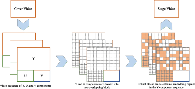
The schematic diagram of joint embedding based on the Y and U components. Orange blocks represent PCA-selected regions, and white blocks represent unselected regions
-
(2)
Decode C1 to get the Y component and U component. The Y component is divided into non-overlapping n×n blocks. Divide the U component into n/2×n/2 blocks.
-
(3)
Extract the elements based on DWT and SVD to construct the embedding domain EDY and EDU.
-
(4)
Make principal component analysis and calculate the proportion of the first principal component of each block in the Y component. Then, generate the side information SI according to the predefined threshold T.
-
(5)
Make side information compression to get compressed side information SI′.
-
(6)
According to SI′, select robust elements in EDY to embed the scrambled secret message based on QIM.
-
(7)
Calculate the proportion of the first principal component of each frame in the U component. Select the first k frames with larger proportions as robust frames. Generate the protocol to label the k frames. The length of the generated protocol is equal to the number of video frames.
-
(8)
The protocol and compressed side information are spliced together. Then, encode spliced information based on BCH codes to eliminate the error bits in the lossy transmission.
-
(9)
Embed the encoded information into U components of selected k frames based on QIM.
-
(10)
Reconstruct modulated Y and U components utilizing inverse SVD and DWT. By setting the CRF value as 0, encode modulated Y and U components combining with the V component to generate the stego video S.

The message extraction is an inverse process of message embedding. The specific extraction process is explained as follows.
-
(1)
Obtain the transcoded video S′ from the target channel. Decode S′ to get the Y and U components.
-
(2)
The Y component is divided into non-overlapping n×n blocks. Divide the U component into non-overlapping n/2×n/2 blocks.
-
(3)
Extract the elements based on DWT and SVD to construct the embedding domain EDY and EDU.
-
(4)
Extract the encoded information with fixed length in EDU. Decode it based on BCH codes to generate the protocol. Then, determine selected k frames.
-
(5)
Extract the encoded side information from the k frames in EDU. Decode it to generate the compressed side information SI′.
-
(6)
According to SI′, determine the extraction regions and select robust elements in EDY.
-
(7)
Extract the scrambled secret message from selected elements based on QIM. Anti-scramble it to get the secret message.
4 Experiments
In this section, extensive experiments are conducted to test the effectiveness of our proposed method. Six setups are elaborately designed from four aspects of robustness, security performance, embedding capacity, and visual quality. Setup 1 and setup 2 are intended to run the robustness test on various simulated and social media channels. Setup 3 is designed to check the security of our proposed method in lossless and lossy cases. Setup 4 is aimed to check our method’s embedding capacity. Then, setup 5 is designed to evaluate the visual quality of stego videos. Finally, setup 6 is aimed to analyze the computational complexity.
4.1 Source videos
The video dataset contains 100 videos with a resolution of 1080p. These videos in the dataset are public and downloaded from YouTube, covering sports, news, advertising, films, and other aspects. Their durations vary from 30 s to 10 min. Each video sequence is stored in the 4:2:0 chroma sampling format (YUV420p). The cover video dataset Dc and Ds are made based on these 100 videos for the whole experimental validation. In order to generate the dataset Dc with different resolutions and bitrates, 10 video clips are randomly selected from these 100 videos, with 300 frames per video clip. Then, video clips are transcoded to generate three groups of videos with resolutions of 1080p, 720p, and 480p. Besides, each group of videos is compressed to various bitrates by setting a CRF value of 16, 20, or 24. Thus, Dc includes 90 (10×3×3) videos where the h264 encoder is used and the framerate is set to 30 frames per second. To enlarge the dataset Dc for the steganalysis test, extra 10 video clips are selected. The dataset Ds is generated with the same process to build Dc, which includes 180 (20×3×3) videos.
4.2 Setups for performance evaluation
in total, six setups are elaborately designed to test the effectiveness of our proposed method.
4.2.1 Setup 1
In this setup, the robustness of our proposed method is assessed on different simulated channels. The robust steganographic method [22] is leveraged for comparison, denoted as Fan’s method. Besides, to validate the effectiveness of PCA selection, the embedding method without PCA selection is also realized as a basic method, called non-PCA method. We construct five lossy channels utilizing two rate control parameters (the CRF and QP). The transcoding parameters of the five channels are shown in Tables 1 and 2. Secret messages used for embedding are binary sequences randomly generated. Besides, we use BCH codes to eliminate error bits. Secret messages are encoded by three BCH codes (7,4,1), (15,5,3), and (31,6,7). All stego videos created in the setup are grouped by the resolution, steganographic method, and BCH code.
The robustness of steganographic methods against video transcoding is measured by the average BER \(\overline {R}_{\mathrm {e}}\) and successful extraction rate Rs. Rs reflects the success rate of covert communication through lossy channels and is defined as:
where Ns denotes the number of videos with the BER of 0, and N denotes the total number of videos in each group.
4.2.2 Setup 2
This setup is intended to evaluate the robustness of steganographic methods on social media channels. In this setup, two popular social media sites, YouTube and Vimeo, are chosen to test the practicability of our proposed method. Their transcoding parameters are unavailable for us. Other experimental settings are the same as setup 1.
4.2.3 Setup 3
This setup is designed to evaluate the security of our proposed method. Our proposed method is based on the spatial-transform domain. However, there is no video steganalysis method specifically for the spatial-transform domain. Thus, steganalysis based on subtractive pixel adjacency matrix (SPAM) features [39] is realized. Meanwhile, a steganalytic algorithm to detect DCT-based data hiding methods for H.264/AVC videos [40] is realized, and video DCT residual (VDCTR) features are extracted. The ensemble classifier [41] is used as the classifier to train the SPAM feature and VDCTR feature, respectively.
In this setup, the video dataset Ds is used to generate the steganalysis samples. In each video, the eight-frame GOP structure consisting of an intra frame followed by seven inter frames is adopted. The SPAM and VDCTR features are extracted from the intra frame of the eight-frame GOP structure. The embedding rate is measured by bits per coefficient (bpc). The coefficient refers to the value of the block feature extracted from a pixel block, which is taken as the cover element to embed secret messages. The embedding rate represents the proportion of coefficients carrying message bits. The used embedding rate is within {0 bpc, 0.1 bpc, 0.2 bpc, 0.3 bpc} to build the training set and test set. The training set consists of 50% randomly selected cover-stego pairs. It is used to build a steganalyzer based on a given steganalytic feature set. The test set comprises 50% remaining cover-stego pairs and is used for classification. The quantization step size is elaborately adjusted to ensure the same level of robustness between our method and Fan’s method. The receiver and observer can only access the transcoded videos in the hidden communication based on social media. The original stego videos are only available for the sender. Thus, it is necessary to make steganalysis on both cover-stego pairs and transcoded cover-stego pairs. In this way, we can comprehensively evaluate our method’s security in practice. In this setup, the steganalysis samples are grouped by the steganographic method, embedding rate, and transmission scenario.
The out of bag (OOB) error EOOB of the steganalysis classifier is considered as the security evaluation criteria, EOOB is an unbiased estimate of the minimum overall detection error rate PE. PE is described as:
where PFA and PMD are the probabilities of two kinds of detection error, the false alarm PFA is that cover samples are classified as stego samples, and the missed detection PMD is that stego samples are classified as cover samples. The detection error rate PE is defined as the average value of PFA and PMD. The larger EOOB equals better security performance against steganalysis.
4.2.4 Setup 4
This setup is designed to reflect the embedding capacity of our method. Cao’s algorithm [42] is implemented, which is a non-robust steganographic method based on motion vectors. Its embedding capacity is used as a baseline to reflect the requirements of actual hidden communication. Besides, Fan’s method [22] is also realized for comparison under the same block size. Under full embedding, the average payload rate \( \overline {P}_{\mathrm {e}} \) of the video set Dc is calculated as:
where \( P_{\mathrm {e}}^{i} \) denotes the payload rate of ith video, mi denotes the length of the secret message embedded in ith video, and the size of ith video is denoted by ci. Here, we use the payload rate to measure the embedding capacity instead of bits per frame (bpf), which can rule out the effect of video resolution on the final result.
It is worth mentioning that we calculate the average payload rate \( \overline {P}_{\mathrm {e}} \) after messages are decoded by BCH code (31,6,7) to highlight the embedding capacity of steganographic methods in the reliable hidden communication scenario.
4.2.5 Setup 5
In this setup, Fan’s method [22] is also realized for comparison. In order to make them consistent in the robustness performance, the quantization step size is elaborately adjusted. Following the same embedding process, the cover-stego pairs are generated based on the dataset Dc. The embedding rate of cover videos is 0 bpc, and stego videos are 1 bpc. Then, both PSNR and SSIM of cover-stego pairs are calculated to evaluate the visual quality of stego videos.
4.2.6 Setup 6
This setup is designed to analyze the computational complexity of non-PCA method, proposed method, and Fan’s method. The experimental platform is MATLAB R2019a, and the used CPU is Intel Xeon Bronze 3106 Processor with a base frequency of 1.7 GHz. In the process of message embedding and extraction, the average time consumed per frame is used to evaluate the computational complexity of these three methods. The embedding time and extraction time are calculated by:
where n is the number of frames in a video, and Temb and Text refer to the time consumed by message embedding and extraction, respectively.
4.3 Parameters discussion
Our proposed method has three important parameters: the block size, quantization step size Δ2 of QIM, and threshold T of PCA selection. They should be elaborately determined to obtain good experimental performance. These parameters are interrelated and have different effects on our method.
4.3.1 Block size
In steganographic methods based on block features, the size of blocks is an essential factor affecting the maximum embedding capacity and visual distortion. The smaller the size of blocks is, the larger the maximum embedding capacity is. However, the smaller blocks could cause more severe video flickers and greater visual distortion. Figure 10a illustrates the relationship of quantization step size and the probability of incorrect QIM decoding, Fig. 10b illustrates the relationship of quantization step size and MSE of cover-stego pairs, under the block size of 8×8, 16×16, or 32×32. The probability of incorrect QIM decoding is negatively correlated with the algorithm’s robustness. As could be observed in Fig. 10a, the quantization step size of 8×8 blocks is close to 16×16 blocks and smaller than 32×32 blocks under the same probability of incorrect QIM decoding. A larger Δ2 is needed to achieve the same level of robustness when the block size is 32×32. As shown in Fig. 10b, the MSE of 16×16 blocks is smaller than 8×8 blocks under the same quantization step size. The greater visual distortion is introduced when the block size is 8×8. The experimental results have shown that 16×16 blocks achieve better performance than 32×32 and 8×8 blocks in terms of robustness and visual quality.

a, b The relationship of quantization step size, probability of incorrect QIM decoding, and MSE of the cover-stego pairs, under the block size of 8×8, 16×16, or 32×32. The robustness is negatively correlated with the probability of incorrect QIM decoding. The MSE represents the difference between cover videos and stego videos
4.3.2 Quantization step size
The quantization step size Δ2 is one of the significant factors determining the robustness of steganographic methods based on QIM. In general, the larger Δ2 is, the stronger the robustness is, but the worse the visual quality is. As shown in Fig. 11, the larger the quantization step size Δ2 is, the smaller the weighted sum of MSE and incorrect QIM decoding probability is until the quantization step size is equal to 42. Theoretically, there is a minimum weighted sum of MSE and incorrect QIM decoding probability for each video to determine the most proper Δ2. The most proper Δ2 can make a tradeoff between robustness and visual quality. However, it is not worthy to calculate the quantization step size of each video when a batch of videos needs to be embedded with messages. The quantization step size within [35,45] is appropriate under the size of 16×16. In the experiments, Δ2 is simply set as 40.

The weighted sum of MSE and probability of incorrect QIM decoding under the block size of 16×16. The MSE and probability of incorrect QIM decoding are normalized to [0,1]. The weight of MSE is set as 0.35, and the weight of incorrect QIM decoding probability is set as 0.65
4.3.3 Threshold of PCA selection
The threshold T of PCA selection determines which regions are selected to embed secret messages. With the threshold T increasing, the probability of incorrect QIM decoding and the maximum embedding rate are shown in Fig. 12. We can fine-tune T to meet the requirements of various communication scenarios. In the experiments, T is set as 0.997 to improve the robustness as much as possible under the premise of sufficient embedding capacity.

The probability of incorrect QIM decoding and maximum embedding rate under the block size of 16×16 and the quantization step size of 40
5 Experimental results and discussion
In Section 4.2, we design six setups to evaluate our proposed method comprehensively. This section presents the experimental results corresponding to these six setups. We obtain the robustness performance on simulated channels and social media based on setups 1 and 2. According to the settings in setups 3, 4, 5, and 6, we get the experimental results on security, embedding capacity, visual quality, and computational time, respectively.
5.1 Robustness performance on simulated channels
The experimental settings are introduced in setup 1. The corresponding results are reported in Tables 3 and 4. Table 3 shows the robustness performance over the lossy channel with a CRF value of 16, 22, or 26. Table 4 reports the robustness performance over the lossy channel with a QP value of 22 or 28. The average BER \(\overline {R}_{\mathrm {e}}\) is calculated before BCH decoding. Rs(1), Rs(2), and Rs(3) respectively represent the successful extraction rate of secret messages decoded with BCH codes (7,4,1), (15,5,3) and (31,6,7).
As shown in Tables 3 and 4, the average BER \(\overline {R}_{\mathrm {e}}\) is positively correlated with the CRF and QP value. Thus, the bitrate of video transcoding has a great impact on robust steganography. Under the same lossy channel, the \(\overline {R}_{\mathrm {e}}\) of our method is always lower than the non-PCA method, which indicates the effectiveness of PCA selection. Besides, our method gets better robustness performance than Fan’s method except for the resolution of 480p and the CRF value of 16. Under the resolution of 480p, the data density of this group of videos is so high that the level of transcoding noise has little relation with the content of the pixel block, which results in a better Fan’s strategy than PCA selection strategy. However, on average, the \(\overline {R}_{\mathrm {e}}\) of our method is between 34 and 67% of Fan’s method in Table 3 and between 60 and 83% of Fan’s method in Table 4. After BCH decoding, the success rate of hidden communication gets improved. The Rs with the BCH code (31,6,7) reaches 100% under the CRF value of 26 and 67% under the QP value of 28. Thus, our proposed method provides stronger robustness performance against video transcoding than two remaining methods. Moreover, the applicability to two rate control parameters is demonstrated.
5.2 Robustness performance on social media
Setup 2 explains the experimental settings of the robustness evaluation on social media. The corresponding results are shown in Table 5. It can be observed that our proposed method achieves better robustness performance than the two remaining methods. The average BER \(\overline {R}_{\mathrm {e}}\) is lower than other methods both on YouTube and Vimeo. Especially on the Vimeo channel, the \(\overline {R}_{\mathrm {e}}\) of our method is less than 53% of Fan’s method. The successful extraction rate Rs with the BCH code (31,6,7) is up to 67% on the YouTube channel and 100% on the Vimeo channel. Thus, our proposed method achieves more robustness and it is more reliable than two other methods. Besides, the \(\overline {R}_{\mathrm {e}}\) on Vimeo is much lower than \(\overline {R}_{\mathrm {e}}\) on YouTube. This is because the used codec of YouTube set a lower coding rate than Vimeo’s codec to transcode videos. In this experiment, the coding rate of output videos on YouTube is about half that on Vimeo.
5.3 Security performance
According to the settings in setup 3, we conduct the security experiment, and the experimental results are reported in Table 6. PE(1) represents the detection error rate of the cover-stego pairs that are not transcoded. PE(2) denotes the detection error rate of the cover-stego pairs that are transcoded by the same video transcoder with the CRF value of 26.
As shown in Table 6, the detection error rate PE increases with the embedding rate increasing. The length of messages is one of the important factors that impair the algorithm’s security. Under the same embedding rate, the PE of our proposed method is bigger than Fan’s method. VDCTR steganalyzer has worse steganalytic performance than SPAM steganalyzer. It may be that VDCTR is a special steganalyzer for DCT coefficients. In the lossless scenario, the average PE of SPAM is 0.1126, and VDCTR is 0.1499. In the lossy scenario, the average PE of SPAM is 0.2655, and VDCTR is 0.3865. They are higher than the average PE of Fan’s method. Thus, our proposed method has better security performance than Fan’s method. There are only transcoded videos available for the observer on social media channels. The average PE in the lossy scenario is more worthy of attention. Thus, our method can provide satisfactory security performance against steganalysis on social media channels.
5.4 Embedding capacity
The experimental settings for the embedding capacity test are introduced in setup 4. The experimental results are shown in Fig. 13. The actual embedding capacity of our proposed method is calculated after secret messages are decoded by the BCH code (31,6,7).

The average payload rate \( \overline {P}_{\mathrm {e}} \) of three group of videos with resolutions of 480p, 720p, and 1080p
As could be observed from Fig. 13, the average payload rate \( \overline {P}_{\mathrm {e}} \) of our proposed method is higher than Fan’s method. Compared with videos of 480p and 720p, 1080p videos have higher embedding capacity. Under the resolution of 1080p, the \( \overline {P}_{\mathrm {e}} \) of our method is even higher than Cao’s method. It may be that the encoding efficiency of 1080p videos is higher than 480p and 720p videos, encoding one pixel needs fewer bits. Thus, our proposed method provides a large embedding capacity, which is satisfactory for hidden communication based on social media.
5.5 Visual quality
The experimental settings are described in setup 5. The corresponding results are shown in Fig. 14. It could be observed that PSNR and SSIM decrease with the video resolution increasing. This may be because 1080p videos embed longer messages than 480p and 720p videos. The length of messages embedded into a video has an impact on the visual quality of this video. Under the same robustness performance, both the PSNR and SSIM of our method are higher than Fan’s method. Thus, our method provides better visual fidelity than Fan’s method.

a, b The PSNR and SSIM of the cover-stego pairs with resolutions of 480p, 720p, and 1080p
5.6 Computational time
According to the settings in setup 6, we conduct the computational complexity test, and the experimental results are shown in Table 7. Obviously, the computational time is related to the video resolution. At the resolution of 480p, the average embedding and extraction times are 1.56 s per frame and 0.48 sper frame, respectively. 720p video takes about three times as long as 480p video, with the embedding and extraction times of 4.7 and 1.44 s per frame. Experimental results confirm that SVD is time-consuming. Our proposed method even consumes more time than the other two methods due to the joint embedding of Y and U components. In practice, we can introduce multi-thread technology and implement our method based on C/C++ language to shorten the embedding and extraction time.
6 Conclusions
In this paper, we propose robust video steganography against video transcoding for social media sharing. First, robust embedding regions are adaptively selected based on PCA. Second, dual-channel joint embedding based on the Y and U components is achieved to sync the embedding and extraction regions. Third, video preprocessing is conducted to generate cover videos by imitating TCM. At last, BCH codes are used to eliminate error bits. In order to verify the robustness and applicability of our method, extensive experiments are executed on local simulated channels, YouTube, and Vimeo. Experimental results show that our proposed method can effectively resist video transcoding. It is more robust and secure than some existing methods to realize reliable hidden communication based on social media, such as YouTube and Vimeo.
There is no denying that our method has some limitations. For example, the proposed method is robust against video transcoding but non-robust against geometric attacks. The computational time is long because of the usage of SVD. In the future, we will introduce multi-thread technology to shorten the embedding and extraction time of our method. Besides, we will explore optimized embedding methods to further improve the robustness and security. Using other spatial transform domain coefficients for robust steganography is also worthy of exploring.
Availability of data and materials
The datasets used and/or analyzed during the current study are available from the corresponding author on reasonable request.
Abbreviations
- STC:
-
Syndrome Trellis Code
- RS:
-
Reed-Solomon
- DCT:
-
Discrete cosine transform
- DWT:
-
Discrete wavelet transform
- SVD:
-
Singular value decomposition
- BCH:
-
Bose-Chaudhuri-Hocquenghem
- BER:
-
Bit error rate
- PCA:
-
Principal component analysis
- QIM:
-
Quantized index modulation
- QP:
-
Quantization parameter
- GOP:
-
Group of pictures
- CRF:
-
Constant rate factor
- MSE:
-
Mean square error
- RLE:
-
Run-length encoding
- TCM:
-
Transport channel matching
- SSIM:
-
Structural similarity
- PSNR:
-
Peak signal to noise ratio
- VDCTR:
-
Video DCT residuals
- SPAM:
-
Subtractive pixel adjacency matrix
- OOB:
-
Out of bag
References
Cisco, Cisco Annual internet report (2018–2023) White Paper (2020). https://www.cisco.com/c/en/us/solutions/collateral/executive-perspectives/annual-internet-report/white-paper-c11-741490.html. Accessed 9 Mar 2019.
X. Zhao, C. Yang, F. Liu, in International Workshop on Digital Watermarking. On the sharing-based model of steganography (SpringerNew York, 2020), pp. 94–105.
C. Kin-Cleaves, A. D. Ker, in IEEE International Workshop on Information Forensics and Security (WIFS). Adaptive steganography in the noisy channel with dual-syndrome trellis codes (IEEENew York, 2018), pp. 1–7.
Z. Zhao, Q. Guan, H. Zhang, X. Zhao, Improving the robustness of adaptive steganographic algorithms based on transport channel matching. IEEE Trans. Inf. Forensics Secur.14:, 1843–1856 (2018).
J. Tao, S. Li, X. Zhang, Z. Wang, Towards robust image steganography. IEEE Trans. Circ. Syst. Video Technol.29:, 594–600 (2018).
Y. Zhang, X. Luo, Y. Guo, C. Qin, F. Liu, Multiple robustness enhancements for image adaptive steganography in lossy channels. IEEE Trans. Circ. Syst. Video Technol.30:, 2750–2764 (2019).
L. Zhao, W. Zhong, in IEEE International Conference on Communication Software and Networks. A novel steganography algorithm based on motion vector and matrix encoding (IEEENew York, 2011), pp. 406–409.
H. Zhang, Y. Cao, X. Zhao, Motion vector-based video steganography with preserved local optimality. Multimed. Tools Appl.75:, 13503–13519 (2016).
P. Wang, H. Zhang, Y. Cao, X. Zhao, in ACM Workshop on Information Hiding and Multimedia Security (IH&MMSec). A novel embedding distortion for motion vector-based steganography considering motion characteristic, local optimality and statistical distribution (ACMNew York, 2016), pp. 127–137.
S. K. Kapotas, A. N. Skodras, in IEEE International Conference on Multimedia and Expo. A new data hiding scheme for scene change detection in h.264 encoded video sequences (ACMNew York, 2008), pp. 277–280.
G. Yang, J. Li, Y. He, Z. Kang, An information hiding algorithm based on intra-prediction modes and matrix coding for h.264/avc video stream. AEU-Int. J. Electron. Commun.65:, 331–337 (2011).
X. Ma, Z. Li, H. Tu, B. Zhang, A data hiding algorithm for h.264/avc video streams without intra-frame distortion drift. IEEE Trans. Circ. Syst. Video Technol.20:, 1320–1330 (2010).
K. Dasgupta, J. Mandal, P. Dutta, Hash based least significant bit technique for video steganography (hlsb). Int. J. Secur. Priv. Trust Manag.1:, 1–11 (2012).
O. Cetin, A. T. Ozcerit, A new steganography algorithm based on color histograms for data embedding into raw video streams. Comput. Secur.28:, 670–682 (2009).
H. M. Kelas, O. F. A. Wahab, O. A. Elshakankiry, H. S. El-sayed, Utilization of steganographic techniques in video sequences. Int. J. Comput. Netw. Technol.2:, 17–24 (2014).
R. J. Mstafa, K. M. Elleithy, in IEEE Sarnoff Symposium. A novel video steganography algorithm in dct domain based on hamming and bch codes (IEEENew York, 2016), pp. 208–213.
C. Xu, X. Ping, in IEEE International Conference on Image and Graphics. A steganographic algorithm in uncompressed video sequence based on difference between adjacent frames (IEEENew York, 2007), pp. 97–302.
R. J. Mstafa, K. M. Elleithy, in IEEE Wireless Telecommunications Symposium (WTS). A high payload video steganography algorithm in DWT domain based on bch codes (15, 11) (IEEENew York, 2015), pp. 1–8.
R. Esfahani, M. A. Akhaee, Z. Norouzi, A fast video watermarking algorithm using dual tree complex wavelet transform. Multimed. Tools Appl.78:, 16159–16175 (2019).
R. J. Mstafa, K. M. Elleithy, E. Abdelfattah, A robust and secure video steganography method in DWT-DCT domains based on multiple object tracking and ecc. IEEE Access. 5:, 5354–5365 (2017).
M. Dalal, M. Juneja, A secure and robust video steganography scheme for covert communication in h.264/avc. Multimed. Tools Appl.80:, 14383–14407 (2021).
P. Fan, H. Zhang, Y. Cai, P. Xie, X. Zhao, in ACM Workshop on Information Hiding and Multimedia Security (IH&MMSec). A robust video steganographic method against social networking transcoding based on steganographic side channel (ACMNew York, 2020), pp. 127–137.
T. Wiegand, G. J. Sullivan, G. Bjontegaard, A. Luthra, Overview of the H.264/AVC video coding standard. IEEE Trans. Circ. Syst. Video Technol.13(7), 560–576 (2003).
G. J. Sullivan, J. -R. Ohm, W. -J. Han, T. Wiegand, Overview of the high efficiency video coding (HEVC) standard. IEEE Trans. Circ. Syst. Video Technol.22:, 1649–1668 (2012).
R. Liu, T. Tan, An svd-based watermarking scheme for protecting rightful ownership. IEEE Trans. Multimed.4:, 121–128 (2002).
J. Zhang, J. Schroeder, T. Cooke, N. Redding, T. Tang, in IEEE Visual Communications and Image Processing. Singular value features of images (IEEENew York, 2000), pp. 894–903.
J. Fridrich, D. Soukal, Matrix embedding for large payloads. IEEE Trans. Inf. Forensic Secur.1:, 390–395 (2006).
Y. Kim, Z. Duric, D. Richards, in International Workshop on Information Hiding. Modified matrix encoding technique for minimal distortion steganography (SpringerNew York, 2006), pp. 314–327.
T. Filler, J. Judas, J. Fridrich, Minimizing additive distortion in steganography using Syndrome-Trellis Codes. IEEE Trans. Inf. Forensic Secur.6:, 920–935 (2011).
B. Chen, G. W. Wornell, in IEEE International Conference on Acoustics, Speech, and Signal Processing. An information-theoretic approach to the design of robust digital watermarking systems, (1999), pp. 2061–2064.
Q. Li, I. J. Cox, Using perceptual models to improve fidelity and provide resistance to valumetric scaling for quantization index modulation watermarking. IEEE Trans. Inf. Forensic Secur.2:, 127–139 (2007).
A. Hocquenghem, Codes correcteurs d’erreurs. Chiffres. 2:, 147–156 (1959).
R. C. Bose, D. K. Ray-Chaudhuri, On a class of error correcting binary group codes. Inf. Control. 3:, 68–79 (1960).
I. S. Reed, G. Solomon, Polynomial codes over certain finite fields. J. Soc. Ind. Appl. Math.8:, 300–304 (1960).
Z. Ni, Y. Q. Shi, N. Ansari, W. Su, Q. Sun, X. Lin, Robust lossless image data hiding designed for semi-fragile image authentication. IEEE Trans. Circ. Syst. Video Technol.18:, 497–509 (2008).
V. Sachnev, H. J. Kim, R. Zhang, in ACM Workshop on Multimedia and Security. Less detectable jpeg steganography method based on heuristic optimization and bch syndrome coding (ACMNew York, 2009), pp. 131–140.
Q. Lin, in IEEE International Conference on Anti-Counterfeiting, Security and Identification. An error correction coding combined robust video watermarking algorithm for h.264 standard (IEEENew York, 2013), pp. 1–4.
Y. Zhang, C. Qin, W. Zhang, F. Liu, X. Luo, On the fault-tolerant performance for a class of robust image steganography. Signal Process.146:, 99–111 (2018).
T. Pevny, P. Bas, J. Fridrich, Steganalysis by subtractive pixel adjacency matrix. IEEE Trans. Inf. Forensic Secur.5:, 215–224 (2010).
P. Wang, Y. Cao, X. Zhao, M. Zhu, in ACM Workshop on Information Hiding and Multimedia Security (IH&MMSec). A steganalytic algorithm to detect dct-based data hiding methods for h.264/avc videos (ACMNew York, 2017), pp. 123–133.
J. Kodovsky, J. Fridrich, V. Holub, Ensemble classifiers for steganalysis of digital media. IEEE Trans. Inf. Forensic Secur.7:, 432–444 (2012).
Y. Cao, X. Zhao, D. Feng, R. Sheng, in International Workshop on Information Hiding. Video steganography with perturbed motion estimation (SpringerNew York, 2011), pp. 193–207.
Acknowledgements
This work was supported by NSFC under 61872356, 61972390 and 61902391, and National Key Technology Research and Development Program under 2019QY0701.
Funding
This work was supported by NSFC under 61872356, 61972390 and 61902391, and National Key Technology Research and Development Program under 2019QY0701.
Author information
Authors and Affiliations
Contributions
FPA made contributions to the design and implementation of the proposed method and wrote part of the paper. ZH and ZXF wrote the paper as well. The authors read and approved the final manuscript.
Corresponding author
Ethics declarations
Competing interests
The authors declare that they have no competing interests.
Additional information
Publisher’s Note
Springer Nature remains neutral with regard to jurisdictional claims in published maps and institutional affiliations.
Rights and permissions
Open Access This article is licensed under a Creative Commons Attribution 4.0 International License, which permits use, sharing, adaptation, distribution and reproduction in any medium or format, as long as you give appropriate credit to the original author(s) and the source, provide a link to the Creative Commons licence, and indicate if changes were made. The images or other third party material in this article are included in the article’s Creative Commons licence, unless indicated otherwise in a credit line to the material. If material is not included in the article’s Creative Commons licence and your intended use is not permitted by statutory regulation or exceeds the permitted use, you will need to obtain permission directly from the copyright holder. To view a copy of this licence, visit http://creativecommons.org/licenses/by/4.0/.
About this article

Cite this article
Fan, P., Zhang, H. & Zhao, X. Robust video steganography for social media sharing based on principal component analysis. EURASIP J. on Info. Security 2022, 4 (2022). https://doi.org/10.1186/s13635-022-00130-z
Received:
Accepted:
Published:
DOI: https://doi.org/10.1186/s13635-022-00130-z